Storage Options
The storage is a core component in a data center. A storage device uses magnetic, optic, or solid state media. Disks, tapes, and diskettes use magnetic media, whereas CD/DVD uses optical media for storage. Removable Flash memory or Flash drives are examples of solid state media.
In the past tapes were the most popular storage option for backups because of their low cost. However, tapes have various limitations in terms of performance and management as listed here:
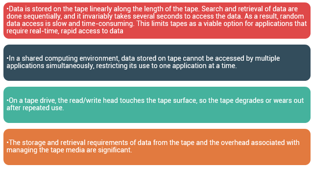
Due to these limitations and availability of low-cost disk drives, tapes are no longer a preferred choice as a backup destination for enterprise-class data centers.
Optical disc storage is popular in small, single-user computing environments. It is frequently used by individuals to store photos or as a backup medium on personal or laptop computers. It is also used as a distribution medium for small applications, such as games, or as a means to transfer small amounts of data from one computer to another.
Optical discs have limited capacity and speed, which limit the use of optical media as a business data storage solution. The capability to write once and read many (WORM) is one advantage of optical disc storage. A CD-ROM is an example of a WORM device. Optical discs, to some degree, guarantee that the content has not been altered. Therefore, it can be used as a low-cost alternative for long-term storage of relatively small amounts of fixed content that do not change after it is created. Collections of optical discs in an array, called a jukebox, are still used as a fixed-content storage solution. Other forms of optical discs include CD-RW, Blu-ray disc, and other variations of DVD.
Disk drivesare the most popular storage medium used in modern computers for storing and accessing data for performance-intensive, online applications. Disks support rapid access to random data locations. This means that data can be written or retrieved quickly for a large number of simultaneous users or applications. In addition, disks have a large capacity. Disk storage arrays are configured with multiple disks to provide increased capacity and enhanced performance.
Flash drives (or solid stated drives -SSDs) uses semiconductor media and provides high performance and low power consumption. Flash drives are discussed in detail later in this module.
Disk Drive Components
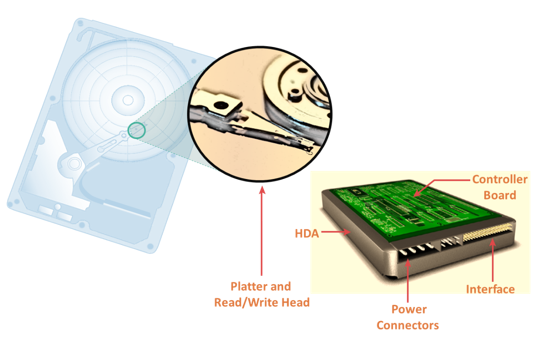
The key components of a hard disk drive are platter, spindle, read-write head, actuator arm assembly, and controller board. I/O operations in a HDD is performed by rapidly moving the arm across the rotating flat platters coated with magnetic particles. Data is transferred between the disk controller and magnetic platters through the read-write (R/W) head which is attached to the arm. Data can be recorded and erased on magnetic platters any number of times.
- A typical HDD consists of one or more flat circular disks called platters. The data is recorded on these platters in binary codes (0s and 1s). The set of rotating platters is sealed in a case, called Head Disk Assembly (HDA). A platter is a rigid, round disk coated with magnetic material on both surfaces (top and bottom). The data is encoded by polarizing the magnetic area, or domains, of the disk surface. Data can be written to or read from both surfaces of the platter. The number of platters and the storage capacity of each platter determine the total capacity of the drive.
- A spindle connects all the platters and is connected to a motor. The motor of the spindle rotates with a constant speed. The disk platter spins at a speed of several thousands of revolutions per minute (rpm). Common spindle speeds are 5,400 rpm, 7,200 rpm, 10,000 rpm, and 15,000 rpm. The speed of the platter is increasing with improvements in technology; although, the extent to which it can be improved is limited.
- Read/Write (R/W) heads, read and write data from or to platters. Drives have two R/W heads per platter, one for each surface of the platter. The R/W head changes the magnetic polarization on the surface of the platter when writing data. While reading data, the head detects the magnetic polarization on the surface of the platter. During reads and writes, the R/W head senses the magnetic polarization and never touches the surface of the platter. When the spindle is rotating, there is a microscopic air gap maintained between the R/W heads and the platters, known as the head flying height. This air gap is removed when the spindle stops rotating and the R/W head rests on a special area on the platter near the spindle. This area is called the landing zone. The landing zone is coated with a lubricant to reduce friction between the head and the platter. The logic on the disk drive ensures that heads are moved to the landing zone before they touch the surface. If the drive malfunctions and the R/W head accidentally touches the surface of the platter outside the landing zone, a head crashoccurs. In a head crash, the magnetic coating on the platter is scratched and may cause damage to the R/W head. A head crash generally results in data loss.
- R/W heads are mounted on the actuator arm assembly, which positions the R/W head at the location on the platter where the data needs to be written or read. The R/W heads for all platters on a drive are attached to one actuator arm assembly and move across the platters simultaneously.
- The controller is a printed circuit board, mounted at the bottom of a disk drive. It consists of a microprocessor, internal memory, circuitry, and firmware. The firmware controls the power to the spindle motor and the speed of the motor. It also manages the communication between the drive and the host. In addition, it controls the R/W operations by moving the actuator arm and switching between different R/W heads, and performs the optimization of data access.
Physical Disk Structure
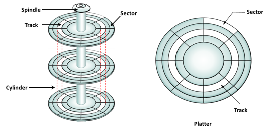
Data on the disk is recorded on tracks, which are concentric rings on the platter around the spindle. The tracks are numbered, starting from zero, from the outer edge of the platter. The number of tracks per inch (TPI) on the platter (or the track density) measures how tightly the tracks are packed on a platter.
Each track is divided into smaller units called sectors. A sector is the smallest, individually addressable unit of storage. The track and sector structure is written on the platter by the drive manufacturer using a low-level formatting operation. The number of sectors per track varies according to the drive type. The first personal computer disks had 17 sectors per track. Recent disks have a much larger number of sectors on a single track. There can be thousands of tracks on a platter, depending on the physical dimensions and recording density of the platter.
Typically, a sector holds 512 bytes of user data; although, some disks can be formatted with larger sector sizes. In addition to user data, a sector also stores other information, such as the sector number, head number or platter number, and track number. This information helps the controller to locate the data on the drive.
A cylinder is a set of identical tracks on both surfaces of each drive platter. The location of R/W heads is referred to by the cylinder number, not by the track number.
Logical Block Addressing
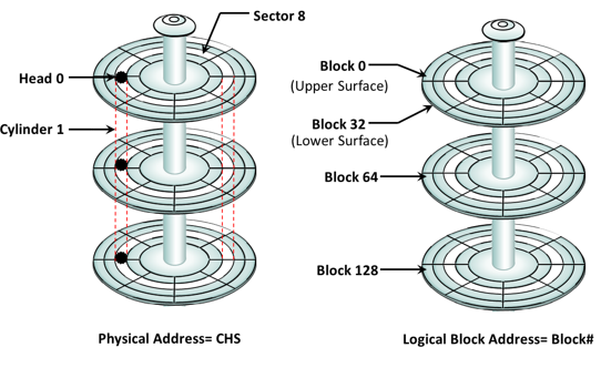
Earlier drives used physical addresses consisting of the cylinder, head, & sector (CHS) number to refer to specific locations on the disk, and the host operating system had to be aware of the geometry of each disk used. Logical block addressing (LBA) has simplified the addressing by using a linear address to access physical blocks of data. The disk controller translates LBA to a CHS address, and the host needs to know only the size of the disk drive in terms of the number of blocks. The logical blocks are mapped to physical sectors on a 1:1 basis.
In the slide, the drive shows eight sectors per track, six heads, and four cylinders. This means a total of 8 ×6 ×4 = 192 blocks, so the block number ranges from 0 to 191. Each block has its own unique address.
Assuming that the sector holds 512 bytes, a 500-GB drive with a formatted capacity of 465.7 GB has in excess of 976,000,000 blocks.
Disk Drive Performance
A disk drive is an electromechanical device that governs the overall performance of the storage system environment. The various factors that affect the performance of disk drives are:
- Seek time
- Rotational latency
- Data transfer rate
Seek Time
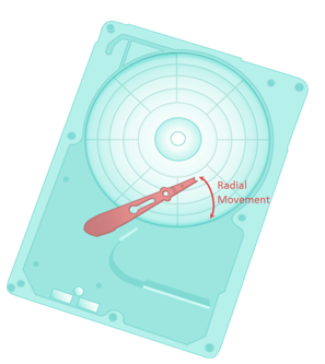 The seek time (also called access time) describes the time taken to position the R/W heads across the platter with a radial movement (moving along the radius of the platter). In other words, it is the time taken to position and settle the arm and the head over the correct track. Therefore, the lower the seek time, the faster the I/O operation. Disk vendors publish the following seek time specifications:
Full Stroke:The time taken by the R/W head to move across the entire width of the disk, from the innermost track to the outermost track.
Average:The average time taken by the R/W head to move from one random track to another, normally listed as the time for one-third of a full stroke.
Track-to-Track:The time taken by the R/W head to move between adjacent tracks.
Each of these specifications is measured in milliseconds. The seek time of a disk is typically specified by the drive manufacturer. The average seek time on a modern disk is typically in the range of 3 to 15 milliseconds. Seek time has more impact on the I/O operation of random tracks rather than the adjacent tracks. To minimize the seek time, data can be written to only a subset of the available cylinders. This results in lower usable capacity than the actual capacity of the drive. For example, a 500-GB disk drive is set up to use only the first 40 percent of the cylinders and is effectively treated as a 200-GB drive. This is known as short-stroking the drive.
Rotational Latency
 To access data, the actuator arm moves the R/W head over the platter to a particular track while the platter spins to position the requested sector under the R/W head. The time taken by the platter to rotate and position the data under the R/W head is called rotational latency. This latency depends on the rotation speed of the spindle and is measured in milliseconds. The average rotational latency is one-half of the time taken for a full rotation. Similar to the seek time, rotational latency has more impact on the reading/writing of random sectors on the disk than on the same operations on adjacent sectors.
Average rotational latency is approximately 5.5 msfor a 5,400-rpm drive, and around 2.0 msfor a 15,000-rpm (or 250-rps revolution per second) drive as shown here. Av. rotational latency for 15K rpm or 250 rps (15000/60) drive is = (1/2)/250=2 milliseconds
Data Transfer Rate
The data transfer rate (also called transfer rate) refers to the average amount of data per unit time that the drive can deliver to the HBA. In a read operation, the data first moves from disk platters to R/W heads; then it moves to the drive’s internal buffer. Finally, data moves from the buffer through the interface to the host HBA. In a write operation, the data moves from the HBA to the internal buffer of the disk drive through the drive’s interface. The data then moves from the buffer to the R/W heads. Finally, it moves from the R/W heads to the platters. The data transfer rates during the R/W operations are measured in terms of internal and external transfer rates, as shown in the slide.
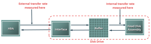
Internal transfer rateis the speed at which data moves from a platter’s surface to the internal buffer (cache) of the disk. The internal transfer rate takes into account factors such as the seek time and rotational latency. External transfer rate is the rate at which data can move through the interface to the HBA. The external transfer rate is generally the advertised speed of the interface, such as 133 MB/s for ATA. The sustained external transfer rate is lower than the interface speed.
I/O Controller Utilization Vs. Response Time
Based on fundamental laws of disk drive performance:
Service time is time taken by the controller to serve an I/O
For performance-sensitive applications disks are commonly utilized below 70% of their I/O serving capability.
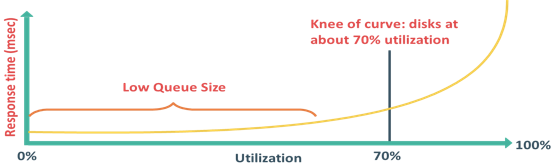
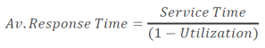
Utilization of a disk I/O controller has a significant impact on the I/O response time. Consider that a disk is viewed as a black box consisting of two elements queue and disk I/O controller. Queue is the location where an I/O request waits before it is processed by the I/O controller and disk I/O controller processes I/Os waiting in the queue one by one.
The I/O requests arrive at the controller at the rate generated by the application. The I/O arrival rate, the queue length, and the time taken by the I/O controller to process each request determines the I/O response time. If the controller is busy or heavily utilized, the queue size will be large and the response time will be high. Based on the fundamental laws of disk drive performance, the relationship between controller utilization and average response time is given as:
Average response time = Service time / (1 –Utilization)
where, service time is the time taken by the controller to serve an I/O.
As the utilization reaches 100 percent that is, as the I/O controller saturates, the response time is closer to infinity. In essence, the saturated component, or the bottleneck, forces the serialization of I/O requests; meaning, each I/O request must wait for the completion of the I/O requests that preceded it. Figure in the slide shows a graph plotted between utilization and response time. The graph indicates that the response time changes are nonlinear as the utilization increases. When the average queue sizes are low, the response time remains low. The response time increases slowly with added load on the queue and increases exponentially when the utilization exceeds 70 percent. Therefore, for performance-sensitive applications, it is common to utilize disks below their 70 percent of I/O serving capability.
Storage Design Based on Application Requirements and Disk Drive Performance
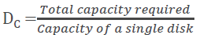
- Disks required to meet an application’s capacity need (DC):
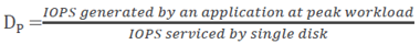
- Disks required to meet application’s performance need (DP):
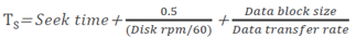
- IOPS serviced by a disk (S) depends upon disk service time (TS):
Determining storage requirements for an application begins with determining the required storage capacity and I/O performance. Capacity can be easily estimated by the size and number of file systems and database components used by applications. The I/O size, I/O characteristics, and the number of I/Os generated by the application at peak workload are other factors that affect performance, I/O response time and design of storage system.
The disk service time (TS) for an I/O is a key measure of disk performance; TS, along with disk utilization rate (U), determines the I/O response time for an application. As discussed earlier the total disk service time is the sum of the seek time, rotational latency, and transfer time.
Note that transfer time is calculated based on the block size of the I/O and given data transfer rate of a disk drive—for example, an I/O with a block size of 32 KB and given disk data transfer rate 40MB/s; the transfer time will be 32 KB / 40 MB.
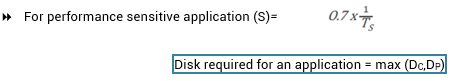
TS determines the time taken by the I/O controller to serve an I/O, therefore, the maximum number of I/Os serviced per second or IOPS is (1/ TS).
The IOPS calculated above represents the IOPS that can be achieved at potentially high levels of I/O controller utilization (close to 100 percent). If the application demands a faster response time, then the utilization for the disks should be maintained below 70 percent.
Based on this discussion, the total number of disks required for an application is computed as:
= Max (Disks required for meeting capacity, Disks required for meeting performance)
Consider an example in which the capacity requirement for an application is 1.46 TB. The number of IOPS generated by the application at peak workload is estimated at 9,000 IOPS. The vendor specifies that a 146-GB, 15,000-rpm drive is capable of doing a maximum 180 IOPS.
In this example, the number of disks required to meet the capacity requirements will be 1.46 TB / 146 GB = 10 disks.
To meet the application IOPS requirements, the number of disks required is 9,000 / 180 = 50. However, if the application is response-time sensitive, the number of IOPS a disk drive can perform should be calculated based on 70-percent disk utilization. Considering this, the number of IOPS a disk can perform at 70 percent utilization is 180 x 0.7 = 126 IOPS. Therefore, the number of disks required to meet the application IOPS requirement will be 9,000 / 126 = 72.
As a result, the number of disks required to meet the application requirements will be Max (10, 72) = 72 disks.
The preceding example indicates that from a capacity-perspective, 10 disks are sufficient; however, the number of disks required to meet application performance is 72. To optimize disk requirements from a performance perspective, various solutions are deployed in a real-time environment. Examples of these solutions are disk native command queuing, use of flash drives, RAID, and the use of cache memory.
RAID and cache are detailed in module 3 and 4 respectively.
Enterprise Flash Drives
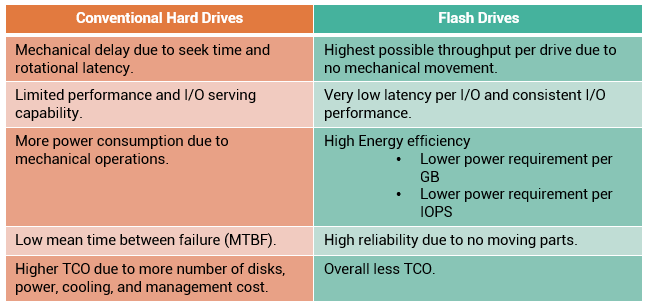
Traditionally, high I/O requirements of an application were met by simply using more disks. Availability of enterprise class flash drives (EFD) has changed the scenario.
Flash drives, also referred as solid state drives (SSDs), are new generation drives that deliver ultra-high performance required by performance-sensitive applications. Flash drives use semiconductor-based solid state memory (flash memory) to store and retrieve data. Unlike conventional mechanical disk drives, flash drives contain no moving parts; therefore, they do not have seek and rotational latencies. Flash drives deliver a high number of IOPS with very low response times. Also, being a semiconductor-based device, flash drives consume less power, compared to mechanical drives. Flash drives are especially suited for applications with small block size and random-read workloads that require consistently low (less than 1 ms) response times. Applications that need to process massive amounts of information quickly, such as currency exchange, electronic trading systems, and real-time data feed processing, benefit from flash drives.
$/GB basis. By implementing flash drives, businesses can meet application performance requirements with far fewer drives (approximately 20 to 30 times less number of drives compared to conventional mechanical drives). This reduction not only provides savings in terms of drive cost, but also translates to savings for power, cooling, and space consumption. Fewer numbers of drives in the environment also means less cost for managing the storage.
Host Access to Storage
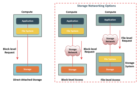
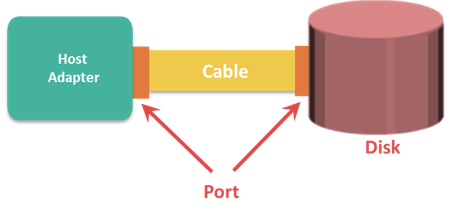
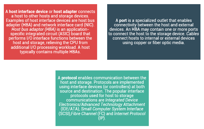
Data is accessed and stored by applications using the underlying infrastructure. The key components of this infrastructure are the operating system (or file system), connectivity, and storage. The storage device can be internal and (or) external to the host. In either case, the host controller card accesses the storage devices using predefined protocols, such as IDE/ATA, SCSI, or Fibre Channel (FC). IDE/ATA and SCSI are popularly used in small and personal computing environments for accessing internal storage. FC and iSCSI protocols are used for accessing data from an external storage device (or subsystems). External storage devices can be connected to the host directly or through the storage network. When the storage is connected directly to the host, it is referred as Direct-Attached Storage (DAS).
Data can be accessed over a network in one of the following ways: block level, file level, or object level. In general, the application requests data from the file system (or operating system) by specifying the filename and location. The file system maps the file attributes to the logical block address of the data and sends the request to the storage device. The storage device converts the logical block address (LBA) to a cylinder-head-sector (CHS) address and fetches the data.
In a block-level access, the file system is created on a host, and data is accessed on a network at the block level. In this case, raw disks or logical volumes are assigned to the host for creating the file system.
In a file-level access, the file system is created on a separate file server or at the storage side, and the file-level request is sent over a network. Because data is accessed at the file level, this method has higher overhead, as compared to the data accessed at the block level. Object-level access is an intelligent evolution, whereby data is accessed over a network in terms of self-contained objects with a unique object identifier. Details of storage networking technologies and deployments are covered in later modules of this course.
Direct-Attached Storage (DAS)
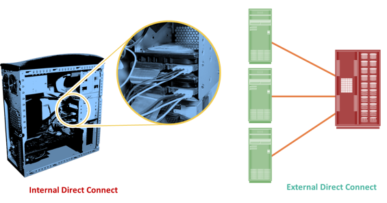
DAS is an architecture in which storage is connected directly to the hosts. The internal disk drive of a host and the directly connected external storage array are examples of DAS. Although the implementation of storage networking technologies is gaining popularity, DAS has remained suitable for localized data access in a small environment, such as personal computing and workgroups. DAS is classified as internal or external, based on the location of the storage device with respect to the host.
In internal DAS architectures, the storage device is internally connected to the host by a serial or parallel bus. The physical bus has distance limitations and can be sustained only over a shorter distance for high-speed connectivity. In addition, most internal buses can support only a limited number of devices, and they occupy a large amount of space inside the host, making maintenance of other components difficult. In external DAS architectures, the host connects directly to the external storage device, and data is accessed at the block level. In most cases, communication between the host and the storage device takes place over a SCSI or FC protocol. Compared to internal DAS, an external DAS overcomes the distance limitations and provides centralized management of storage devices.
DAS Benefits and limitations: DAS requires a relatively lower initial investment than storage networking architectures. The DAS configuration is simple and can be deployed easily and rapidly. It requires fewer management tasks and less hardware and software elements to set up and operate. However, DAS does not scale well. A storage array has a limited number of ports, which restricts the number of hosts that can directly connect to the storage. Therefore, DAS does not make optimal use of resources and, moreover unused resources cannot be easily re-allocated, resulting in islands of over-utilized and under-utilized storage pools.
Concept in Practice
VMware ESXi
The concept in practice covers the product example of compute virtualization. It covers industry’s leading hypervisor software VMware ESXi.
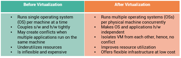
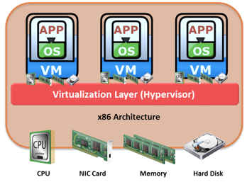
VMware is the leading provider for server virtualization solution. VMware ESXi provides a platform called hypervisor. The hypervisor abstracts CPU, memory, and storage resources to run multiple virtual machines concurrently on the same physical server.
VMware ESXi is a hypervisor that installs on x86 hardware to enable server virtualization. It enables creating multiple virtual machines (VMs) that can run simultaneously on the same physical machine. A VM is a discrete set of files that can be moved, copied, and used as a template. All the files that make up a VM are typically stored in a single directory on a cluster file system called Virtual Machine File System (VMFS). The physical machine that houses ESXi is called ESXi host. The ESXi hosts provide physical resources used to run virtual machines. ESXi has two key components: VMkernel and Virtual Machine Monitor.
VMkernel provides functionality similar to that found in other operating systems, such as process creation, file system management, and process scheduling. It is designed to specifically support running multiple VMs and provide core functionality such as resource scheduling, I/O stacks, and so on.
The virtual machine monitor is responsible for executing commands on the CPUs and performing Binary Translation (BT). A virtual machine monitor performs hardware abstraction to appear as a physical machine with its own CPU, memory, and I/O devices. Each VM is assigned a virtual machine monitor that has a share of the CPU, memory, and I/O devices to successfully run the VM.


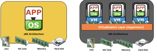
 Users store and retrieve data through applications. The computers on which these applications run are referred to as hostsor compute systems. Hosts can be physical or virtual machines. A compute virtualization software enables creating virtual machines on top of physical compute infrastructure. Compute virtualization and virtual machines are discussed later in this module.
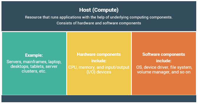
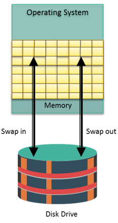 Memory has been, and continues to be, an expensive component of a host. It determines both the size and number of applications that can run on a host. Memory virtualizationenables multiple applications and processes, whose aggregate memory requirement is greater than the available physical memory, to run on a host without impacting each other.
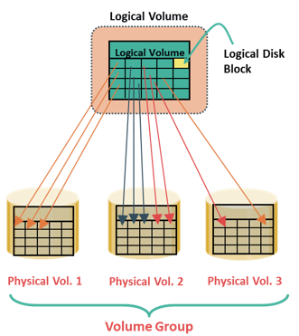 The evolution of Logical Volume Managers (LVMs) enabled dynamic extension of file system capacity and efficient storage management. LVM is software that runs on the compute system and manages logical and physical storage. LVM is an intermediate layer between the file system and the physical disk. It can partition a larger-capacity disk into virtual, smaller-capacity volumes (the process is called partitioning) or aggregate several smaller disks to form a larger virtual volume. (The process is called concatenation).
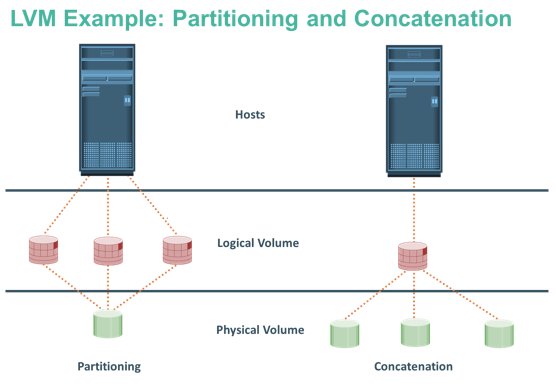
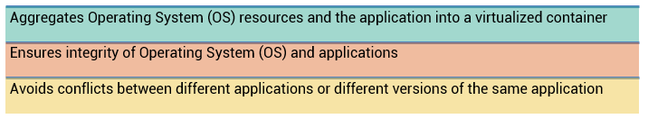
 This technique enables creating portable virtual compute systems called virtual machines (VMs). Each VM runs an operating system and application instance in an isolated manner.