Introduction
This module focuses on RAID and its use to improve performance and protection. It details various RAID implementations, techniques, and levels commonly used. This module also describes the impact of RAID on performance and compares the commonly used RAID levels.
Upon completion of this module, you should be able to:
Introduction
During this lesson the following topics are covered:
Explanation
It is a technique that combines multiple disk drives into a logical unit (RAID set) and provides protection, performance, or both.
Today’s data centers house hundreds of disk drives in their storage infrastructure. Disk drives are inherently susceptible to failures due to mechanical wear and tear and other environmental factors, which could result in data loss. The greater the number of disk drives in a storage array, the greater the probability of a disk failure in the array.
For example, consider a storage array of 100 disk drives, each with an average life expectancy of 750,000 hours. The average life expectancy of this collection in the array, therefore, is 750,000/100 or 7,500 hours. This means that a disk drive in this array is likely to fail at least once in 7,500 hours.
RAID is an enabling technology that leverages multiple drives as part of a set that provides data protection against drive failures. In general, RAID implementations also improve the storage system performance by serving I/Os from multiple disks simultaneously. Modern arrays with flash drives also benefit in terms of protection and performance by using RAID.
In 1987, Patterson, Gibson, and Katz at the University of California, Berkeley, published a paper titled “A Case for Redundant Arrays of Inexpensive Disks (RAID).” This paper described the use of small-capacity, inexpensive disk drives as an alternative to large-capacity drives common on mainframe computers. The term RAID has been redefined to refer to independent disks to reflect advances in the storage technology. RAID technology has now grown from an academic concept to an industry standard and is common implementation in today’s storage arrays.
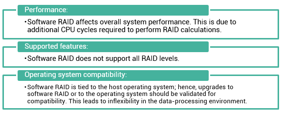
There are two methods of RAID implementation, hardware and software. Both have their advantages and disadvantages. Software RAID uses host-based software to provide RAID functions and is implemented at the operating-system level. Software RAID implementations offer cost and simplicity benefits when compared with hardware RAID. However, they have the following limitations:
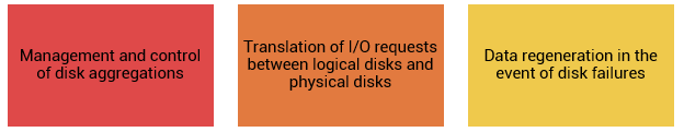
In hardware RAID implementations, a specialized hardware controller is implemented either on the host or on the array. Controller card RAID is a host-based hardware RAID implementation in which a specialized RAID controller is installed in the host, and disk drives are connected to it. Manufacturers also integrate RAID controllers on motherboards. A host-based RAID controller is not an efficient solution in a data center environment with a large number of hosts. The external RAID controller is an array-based hardware RAID. It acts as an interface between the host and disks. It presents storage volumes to the host, and the host manages these volumes as physical drives. The key functions of the RAID controllers are as follows:
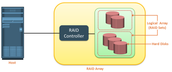
A RAID array is an enclosure that contains a number of disk drives and supporting hardware to implement RAID. A subset of disks within a RAID array can be grouped to form logical associations called logical arrays, also known as a RAID set or a RAID group.
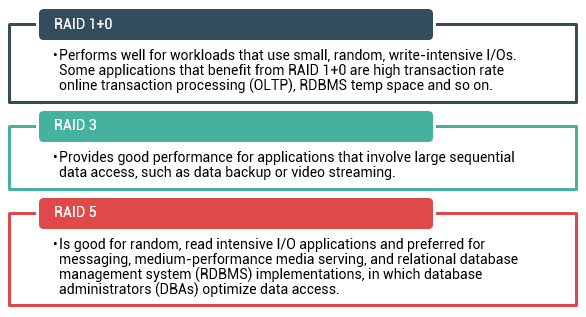
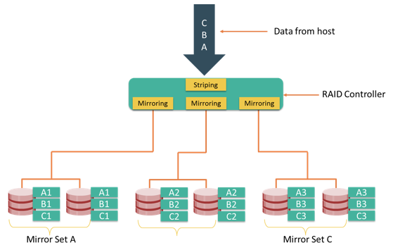
RAID techniques –striping, mirroring, and parity –form the basis for defining various RAID levels. These techniques determine the data availability and performance characteristics of a RAID set.
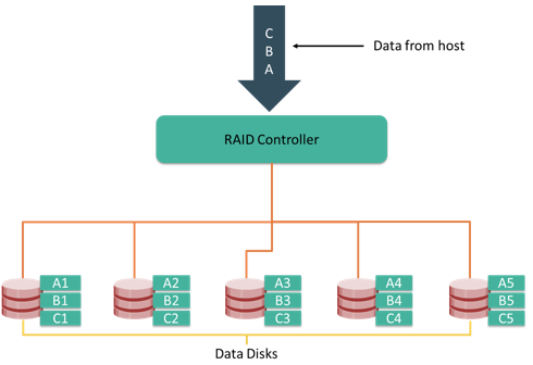
Striping is a technique of spreading data across multiple drives (more than one) in order to use the drives in parallel. All the read-write heads work simultaneously, allowing more data to be processed in a shorter time and increasing performance, compared to reading and writing from a single disk.
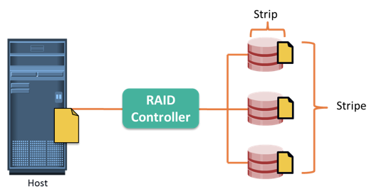
Within each disk in a RAID set, a predefined number of contiguously addressable disk blocks are defined as strip. The set of aligned strips that spans across all the disks within the RAID set is called a stripe. Figure on the slide shows physical and logical representations of a striped RAID set.
Strip size (also called stripe depth) describes the number of blocks in a strip, and is the maximum amount of data that can be written to or read from a single disk in the set, assuming that the accessed data starts at the beginning of the strip. All strips in a stripe have the same number of blocks. Having a smaller strip size means that the data is broken into smaller pieces while spread across the disks.
Stripe size is a multiple of strip size by the number of data disks in the RAID set. For example, in a five disk striped RAID set with a strip size of 64KB, the stripe size is 320 KB (64KB x 5). Stripe width refers to the number of data strips in a stripe. Striped RAID does not provide any data protection unless parity or mirroring is used.
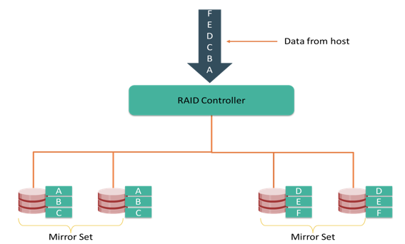
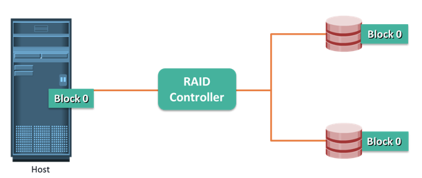
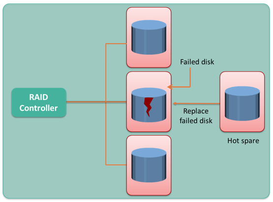
Mirroring is a technique whereby the same data is stored on two different disk drives, yielding two copies of the data. If one disk drive failure occurs, the data is intact on the surviving disk drive and the controller continues to service the host’s data requests from the surviving disk of a mirrored pair.
When the failed disk is replaced with a new disk, the controller copies the data from the surviving disk of the mirrored pair. This activity is transparent to the host.
In addition to providing complete data redundancy, mirroring enables fast recovery from disk failure. However, disk mirroring provides only data protection and is not a substitute for data backup. Mirroring constantly captures changes in the data, whereas a backup captures point-in-time images of the data.
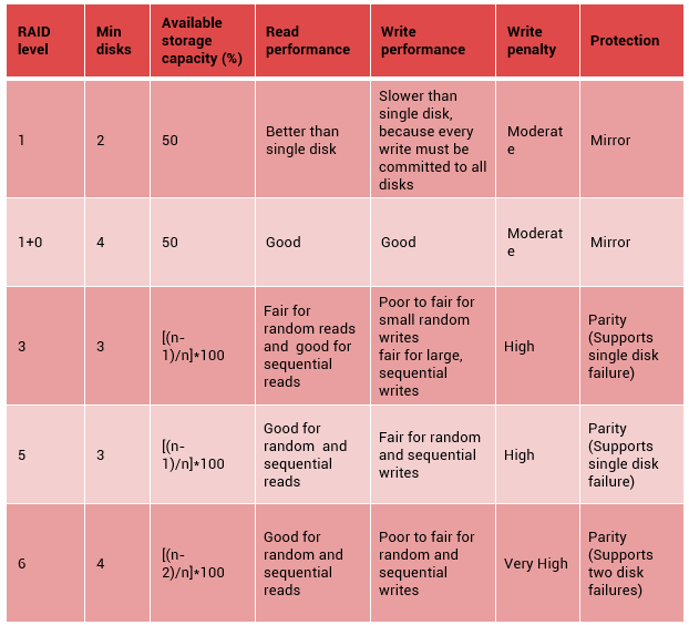
Mirroring involves duplication of data—the amount of storage capacity needed is twice the amount of data being stored. Therefore, mirroring is considered expensive and is preferred for mission-critical applications that cannot afford the risk of any data loss. Mirroring improves read performance because read requests can be serviced by both disks. However, write performance is slightly lower than that in a single disk because each write request manifests as two writes on the disk drives. Mirroring does not deliver the same levels of write performance as a striped RAID.
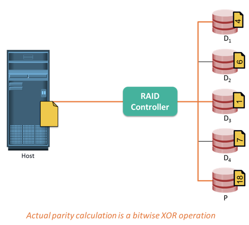
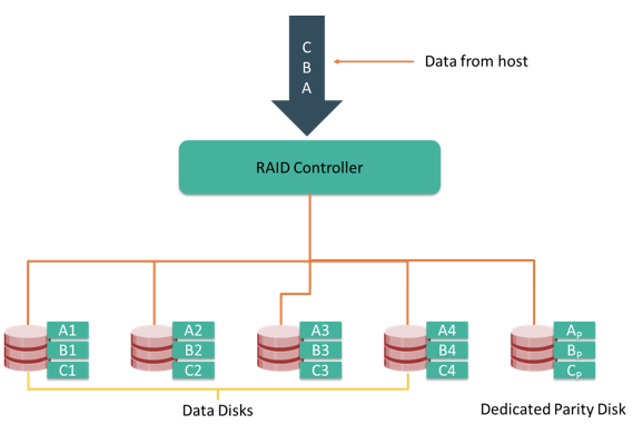
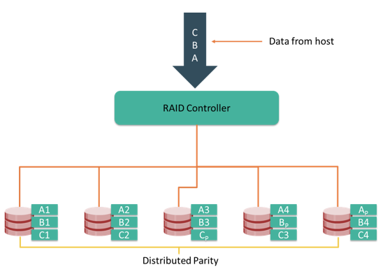
Parity is a method to protect striped data from disk drive failure without the cost of mirroring. An additional disk drive is added to hold parity, a mathematical construct that allows re-creation of the missing data. Parity is a redundancy technique that ensures protection of data without maintaining a full set of duplicate data. Calculation of parity is a function of the RAID controller.
Parity information can be stored on separate, dedicated disk drives or distributed across all the drives in a RAID set. The first four disks in the figure, labeled D1 to D4, contain the data. The fifth disk, labeled P, stores the parity information, which, in this case, is the sum of the elements in each row.
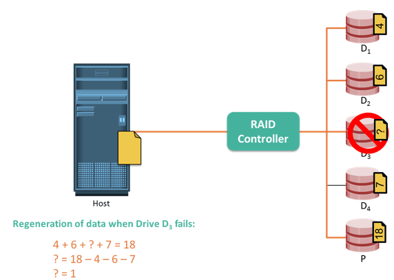
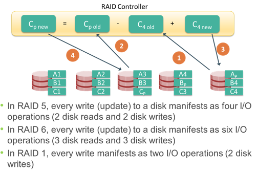
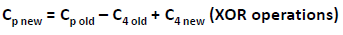
Now, if one of the data disks fails, the missing value can be calculated by subtracting the sum of the rest of the elements from the parity value. Here, for simplicity, the computation of parity is represented as an arithmetic sum of the data. However, parity calculation is a bitwise XOR operation.
Compared to mirroring, parity implementation considerably reduces the cost associated with data protection. Consider an example of a parity RAID configuration with five disks where four disks hold data, and the fifth holds the parity information. In this example, parity requires only 25 percent extra disk space compared to mirroring, which requires 100 percent extra disk space. However, there are some disadvantages of using parity. Parity information is generated from data on the data disk. Therefore, parity is recalculated every time there is a change in data. This recalculation is time-consuming and affects the performance of the RAID array.
For parity RAID, the stripe size calculation does not include the parity strip. For example in a five (4 + 1) disk parity RAID set with a strip size of 64 KB, the stripe size will be 256 KB (64 KB x 4).
Introduction
This lesson focuses on commonly used RAID levels and their comparisons. This lesson also focuses on Hot spare.
Explanation
Application performance, data availability requirements, and cost determine the RAID level selection. These RAID levels are defined on the basis of striping, mirroring, and parity techniques. Some RAID levels use a single technique, whereas others use a combination of techniques. The commonly used RAID levels are listed on the slide.
Commonly used RAID levels are:
RAID 0 configuration uses data striping techniques, where data is striped across all the disks within a RAID set. Therefore it utilizes the full storage capacity of a RAID set. To read data, all the strips are put back together by the controller. When the number of drives in the RAID set increases, performance improves because more data can be read or written simultaneously. RAID 0 is a good option for applications that need high I/O throughput. However, if these applications require high availability during drive failures, RAID 0 does not provide data protection and availability.
RAID 1 is based on the mirroring technique. In this RAID configuration, data is mirrored to provide fault tolerance. A RAID 1 set consists of two disk drives and every write is written to both disks. The mirroring is transparent to the host. During disk failure, the impact on data recovery in RAID 1 is the least among all RAID implementations. This is because the RAID controller uses the mirror drive for data recovery. RAID 1 is suitable for applications that require high availability and cost is no constraint.
Most data centers require data redundancy and performance from their RAID arrays. RAID 1+0 combines the performance benefits of RAID 0 with the redundancy benefits of RAID 1. It uses mirroring and striping techniques and combine their benefits. This RAID type requires an even number of disks, the minimum being four. RAID 1+0 is also known as RAID 10 (Ten) or RAID 1/0. RAID 1+0 is also called striped mirror. The basic element of RAID 1+0 is a mirrored pair, which means that data is first mirrored and then both copies of the data are striped across multiple disk drive pairs in a RAID set. When replacing a failed drive, only the mirror is rebuilt. In other words, the disk array controller uses the surviving drive in the mirrored pair for data recovery and continuous operation. Data from the surviving disk is copied to the replacement disk.
RAID 3 stripes data for performance and uses parity for fault tolerance. Parity information is stored on a dedicated drive so that the data can be reconstructed if a drive fails in a RAID set. For example, in a set of five disks, four are used for data and one for parity. Therefore, the total disk space required is 1.25 times the size of the data disks. RAID 3alwaysreads and writes complete stripes of data across all disks because the drives operate in parallel. There are no partial writes that update one out of many strips in a stripe.Similar to RAID 3, RAID 4 stripes data for high performance and uses parity for improved fault tolerance. Data is striped across all disks except the parity disk in the array. Parity information is stored on a dedicated disk so that the data can be rebuilt if a drive fails. Unlike RAID 3, data disks in RAID 4 can be accessed independently so that specific data elements can be read or written on a single disk without reading or writing an entire stripe. RAID 4 provides good read throughput and reasonable write throughput.
RAID 5 is a versatile RAID implementation. It is similar to RAID 4 because it uses striping. The drives (strips) are also independently accessible. The difference between RAID 4 and RAID 5 is the parity location. In RAID 4, parity is written to a dedicated drive, creating a write bottleneck for the parity disk. In RAID 5, parity is distributed across all disks to overcome the write bottleneck of a dedicated parity disk.
RAID 6 works the same way as RAID 5, except that RAID 6 includes a second parity element to enable survival if two disk failures occur in a RAID set. Therefore, a RAID 6 implementation requires at least four disks. RAID 6 distributes the parity across all the disks. The write penalty (explained later in this module) in RAID 6 is more than that in RAID 5; therefore, RAID 5 writes perform better than RAID 6. The rebuild operation in RAID 6 may take longer than that in RAID 5 due to the presence of two parity sets.
When choosing a RAID type, it is imperative to consider its impact on disk performance and application IOPS. In both mirrored and parity RAID configurations, every write operation translates into more I/O overhead for the disks, which is referred to as a write penalty. In a RAID 1 implementation, every write operation must be performed on two disks configured as a mirrored pair, whereas in a RAID 5 implementation, a write operation may manifest as four I/O operations. When performing I/Os to a disk configured with RAID 5, the controller has to read, recalculate, and write a parity segment for every data write operation.
This slide illustrates a single write operation on RAID 5 that contains a group of five disks. The parity (P) at the controller is calculated as follows:
Whenever the controller performs a write I/O, parity must be computed by reading the old parity (Cpold) and the old data (C4 old) from the disk, which means two read I/Os. Then, the new parity (Cpnew) is computed as follows:
After computing the new parity, the controller completes the write I/O by writing the new data and the new parity onto the disks, amounting to two write I/Os. Therefore, the controller performs two disk reads and two disk writes for every write operation, and the write penalty is 4.
In RAID 6, which maintains dual parity, a disk write requires three read operations: two parity and one data. After calculating both new parities, the controller performs three write operations: two parity and an I/O. Therefore, in a RAID 6 implementation, the controller performs six I/O operations for each write I/O, and the write penalty is 6.
Total IOPS at peak workload is 1200
Read/Write ratio 2:1
Calculate disk load at peak activity for:
Consider an application that generates 1200 IOPS at peak workload, with read/write ratio of 2:1. Calculate disk load at peak activity for RAID 1/0 and RAID 5 configuration.
The table on the slide compare different RAID levels.
Common applications that benefit from different RAID levels.
A hot sparerefers to a spare drive in a RAID array that temporarily replaces a failed disk drive by taking the identity of the failed disk drive. With the hot spare, one of the following methods of data recovery is performed depending on the RAID implementation:
For example, consider a storage array of 100 disk drives, each with an average life expectancy of 750,000 hours. The average life expectancy of this collection in the array, therefore, is 750,000/100 or 7,500 hours. This means that a disk drive in this array is likely to fail at least once in 7,500 hours.
When a new disk drive is added to the system, data from the hot spare is copied to it. The hot spare returns to its idle state, ready to replace the next failed drive. Alternatively, the hot spare replaces the failed disk drive permanently. This means that it is no longer a hot spare, and a new hot spare must be configured on the array.
A hot spare should be large enough to accommodate data from a failed drive. Some systems implement multiple hot spares to improve data availability.
A hot spare can be configured as automatic or user initiated, which specifies how it will be used in the event of disk failure. In an automatic configuration, when the recoverable error rates for a disk exceed a predetermined threshold, the disk subsystem tries to copy data from the failing disk to the hot spare automatically. If this task is completed before the damaged disk fails, the subsystem switches to the hot spare and marks the failing disk as unusable. Otherwise, it uses parity or the mirrored disk to recover the data. In the case of a user-initiated configuration, the administrator has control of the rebuild process. For example, the rebuild could occur overnight to prevent any degradation of system performance. However, the system is at risk of data loss if another disk failure occurs.
Summary
This module covered the two methods of RAID implementation, hardware and software. The three techniques on which the RAID levels are built are striping, mirroring, and parity. The commonly used RAID levels are 0, 1, 1+0, 3, 5, and 6.When choosing a RAID type, it is imperative to consider its impact on disk performance and application IOPS. In both mirrored and parity RAID configurations, every write operation translates into more I/O overhead for the disks, which is referred to as a write penalty .Finally, this module compared different RAID levels based on their cost, performance, and write penalty.
Checkpoint
Bibliographic references