Storage Provisioning
It is the process of assigning storage resources to hosts based on capacity, availability, and performance requirements of applications running on the hosts.
Storage provisioning can be performed in two ways: traditional and virtual. Virtual provisioning leverages virtualization technology for provisioning storage for applications.
Traditional Storage Provisioning
In traditional storage provisioning, physical disks are logically grouped together on which a required RAID level is applied to form a set, called RAID set. The number of drives in the RAID set and the RAID level determine the availability, capacity, and performance of the RAID set. It is highly recommend that the RAID set be created from drives of the same type, speed, and capacity to ensure maximum usable capacity, reliability, and consistency in performance. For example, if drives of different capacities are mixed in a RAID set, the capacity of the smallest drive is used from each disk in the set to make up the RAID set’s overall capacity.
The remaining capacity of the larger drives remains unused. Likewise, mixing higher revolutions per minute (RPM) drives with lower RPM drives lowers the overall performance of the RAID set.
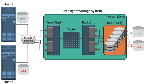
RAID sets usually have a large capacity because they combine the total capacity of individual drives in the set. Logical units are created from the RAID sets by partitioning (seen as slices of the RAID set) the available capacity into smaller units. These units are then assigned to the host based on their storage requirements. Logical units are spread across all the physical disks that belong to that set. Each logical unit created from the RAID set is assigned a unique ID, called a logical unit number (LUN). LUNs hide the organization and composition of the RAID set from the hosts. LUNs created by traditional storage provisioning methods are also referred to as thick LUNs to distinguish them from the LUNs created by virtual provisioning methods.
Figure on the slide shows a RAID set consisting of five disks that have been sliced, or partitioned, into two LUNs: LUN 0 and LUN 1. These LUNs are then assigned to Host1 and Host 2 for their storage requirements.
When a LUN is configured and assigned to a non-virtualized host, a bus scan is required to identify the LUN. This LUN appears as a raw disk to the operating system. To make this disk usable, it is formatted with a file system and then the file system is mounted.
In a virtualized host environment, the LUN is assigned to the hypervisor, which recognizes it as a raw disk. This disk is configured with the hypervisor file system, and then virtual disks are created on it. Virtual disks are files on the hypervisor file system. The virtual disks are then assigned to virtual machines and appear as raw disks to them. To make the virtual disk usable to the virtual machine, similar steps are followed as in a non-virtualized environment. Here, the LUN space may be shared and accessed simultaneously by multiple virtual machines.
Virtual machines can also access a LUN directly on the storage system. In this method the entire LUN is allocated to a single virtual machine. Storing data in this way is recommended when the applications running on the virtual machine are response-time sensitive, and sharing storage with other virtual machines may impact their response time. The direct access method is also used when a virtual machine is clustered with a physical machine. In this case, the virtual machine is required to access the LUN that is being accessed by the physical machine.
LUN Expansion
MetaLUN
It is a method to expand LUNs that require additional capacity or performance.
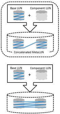
A metaLUN can be created by combining two or more LUNs. A metaLUN consists of a base LUN and one or more component LUNs. MetaLUNs can be either concatenated or striped.
Concatenated expansion simply adds additional capacity to the base LUN. In this expansion, the component LUNs are not required to be of the same capacity as the base LUN. All LUNs in a concatenated metaLUN must be either protected (parity or mirrored) or unprotected (RAID 0). RAID types within a metaLUN can be mixed. For example, a RAID 1/0 LUN can be concatenated with a RAID 5 LUN. However, a RAID 0 LUN can be concatenated only with another RAID 0 LUN. Concatenated expansion is quick but does not provide any performance benefit.
Striped expansion restripes the base LUN’s data across the base LUN and component LUNs. In striped expansion, all LUNs must be of the same capacity and RAID level. Striped expansion provides improved performance due to the increased number of drives being striped.
All LUNs in both concatenated and striped expansion must reside on the same disk-drive type: either all Fibre Channel or all ATA.
Virtual Storage Provisioning
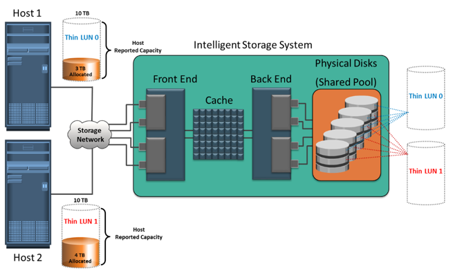
Virtual provisioning enables creating and presenting a LUN with more capacity than is physically allocated to it on the storage array. The LUN created using virtual provisioning is called a thin LUN to distinguish it from the traditional LUN.
Thin LUNs do not require physical storage to be completely allocated to them at the time they are created and presented to a host. Physical storage is allocated to the host “on- demand” from a shared pool of physical capacity. A shared pool is consists of physical disks. A shared pool in virtual provisioning is analogous to a RAID group, which is a collection of drives on which LUNs are created. Similar to a RAID group, a shared pool supports a single RAID protection level. However, unlike a RAID group, a shared pool might contain large numbers of drives. Shared pools can be homogeneous (containing a single drive type) or heterogeneous (containing mixed drive types, such as flash, FC, SAS, and SATA drives).
Virtual provisioning enables more efficient allocation of storage to hosts. Virtual provisioning also enables oversubscription, where more capacity is presented to the hosts than is actually available on the storage array. Both shared pool and thin LUN can be expanded nondisruptively as the storage requirements of the hosts grow. Multiple shared pools can be created within a storage array, and a shared pool may be shared by multiple thin LUNs.
Traditional Provisioning vs. Virtual Provisioning
Administrators typically allocate storage capacity based on anticipated storage requirements. This generally results in the over provisioning of storage capacity, which then leads to higher costs and lower capacity utilization. Administrators often over-provision storage to an application for various reasons such as, to avoid frequent provisioning of storage if the LUN capacity is exhausted, and to reduce disruption to application availability. Over provisioning of storage often leads to additional storage acquisition and operational costs.
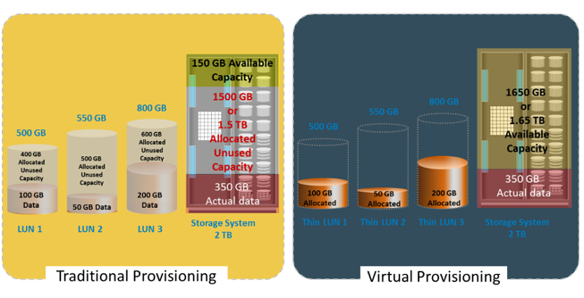
Virtual provisioning addresses these challenges. Virtual provisioning improves storage capacity utilization and simplifies storage management. Figure on the slide illustrates an example, comparing virtual provisioning with traditional storage provisioning.
With traditional provisioning, three LUNs are created and presented to one or more hosts. The total storage capacity of the storage system is 2 TB. The allocated capacity of LUN 1 is 500 GB, of which only 100 GB is consumed, and the remaining 400 GB is unused. The size of LUN 2 is 550 GB, of which 50 GB is consumed, and 500 GB is unused. The size of LUN 3 is 800 GB, of which 200 GB is consumed, and 600 GB is unused. In total, the storage system has 350 GB of data, 1.5 TB of allocated but unused capacity, and only 150 GB of remaining capacity available for other applications.
Now consider the same 2 TB storage system with virtual provisioning. Here, three thin LUNs of the same sizes are created. However, there is no allocated unused capacity. In total, the storage system with virtual provisioning has the same 350 GB of data, but 1.65 TB of capacity is available for other applications, whereas only 150 GB is available in traditional storage provisioning.
Virtual provisioning and thin LUN offer many benefits, although in some cases traditional LUN is better suited for an application. Thin LUNs are appropriate for applications that can tolerate performance variations. In some cases, performance improvement is perceived when using a thin LUN, due to striping across a large number of drives in the pool. However, when multiple thin LUNs contend for shared storage resources in a given pool, and when utilization reaches higher levels, the performance can degrade. Thin LUNs provide the best storage space efficiency and are suitable for applications where space consumption is difficult to forecast. Using thin LUNs benefits organizations in reducing power and acquisition costs and in simplifying their storage management.
Traditional LUNs are suited for applications that require predictable performance. Traditional LUNs provide full control for precise data placement and allow an administrator to create LUNs on different RAID groups if there is any workload contention. Organizations that are not highly concerned about storage space efficiency may still use traditional LUNs.
Both traditional and thin LUNs can coexist in the same storage array. Based on the requirement, an administrator may migrate data between thin and traditional LUNs.
LUN Masking
LUN Masking
It a process that provides data access control by defining which LUNs a host can access
The LUN masking function is implemented on the storage array. This ensures that volume access by hosts is controlled appropriately, preventing unauthorized or accidental use in a shared environment.
For example, consider a storage array with two LUNs that store data of the sales and finance departments. Without LUN masking, both departments can easily see and modify each other’s data, posing a high risk to data integrity and security. With LUN masking, LUNs are accessible only to the designated hosts.
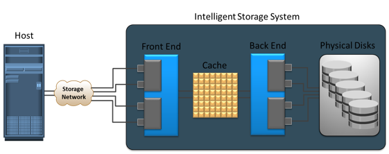
Intelligent storage systems generally fall into one of the following two categories: high-end storage systems, and midrange storage systems.
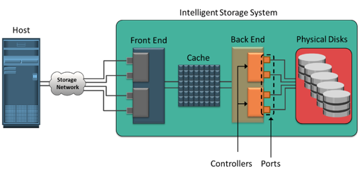
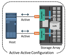
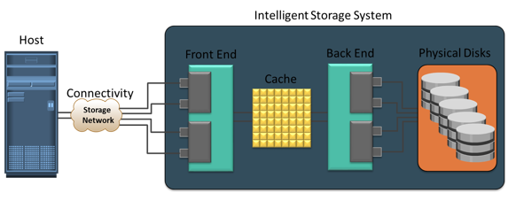
High-end storage systems, referred to as active-active arrays, are generally aimed at large enterprise applications. These systems are designed with a large number of controllers and cache memory. An active-active array implies that the host can perform I/Os to its LUNs through any of the available controllers.
To address enterprise storage needs, these arrays provide the following capabilities:
- Large storage capacity
- Large amounts of cache to service host I/Os optimally
- Fault tolerance architecture to improve data availability
- Connectivity to mainframe computers and open systems hosts
- Availability of multiple front-end ports and interface protocols to serve a large number of hosts
- Availability of multiple back-end controllers to manage disk processing
- Scalability to support increased connectivity, performance, and storage capacity requirements
- Ability to handle large amounts of concurrent I/Os from a number of hosts and applications
- Support for array-based local and remote data replication
In addition to these features, high-end systems possess some unique features that are required for mission-critical applications.
Types of ISS: Midrange Storage Systems
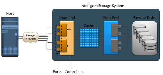
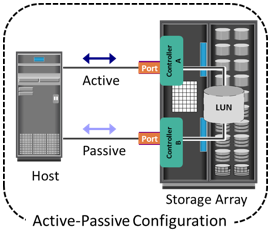 Midrange storage systems are also referred to as active-passive arrays and are best suited for small- and medium-sized enterprise applications. They also provide optimal storage solutions at a lower cost. In an active-passive array, a host can perform I/Os to a LUN only through the controller that owns the LUN.
The host can perform reads or writes to the LUN only through the path to controller A because controller A is the owner of that LUN. The path to controller B remains passive and no I/O activity is performed through this path.
Midrange storage systems are typically designed with two controllers, each of which contains host interfaces, cache, RAID controllers, and interface to disk drives.
Midrange arrays are designed to meet the requirements of small and medium enterprise application; therefore, they host less storage capacity and cache than high-end storage arrays. There are also fewer front-end ports for connection to hosts. However, they ensure high redundancy and high performance for applications with predictable workloads. They also support array-based local and remote replication.
Concept in Practice
 The Concept in Practice covers the product example of intelligent storage system. It covers two products: EMC Symmetrix and EMC VNX.
EMC VNX
- EMC’s midrange storage offering
- Unified storage offering that provides storage for block, file, and object data
- Ideally suited for applications with predictable workloads
EMC Symmetrix VMAX
EMC Symmetrix establishes the highest standards for performance and capacity for an enterprise information storage solution and is recognized as the industry’s most trusted storage platform. Symmetrix offers the highest level of scalability and performance to meet even unpredictable I/O workload requirements. The EMC Symmetrix offering includes Symmetrix Virtual Matrix (VMAX) series.
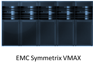 The EMC Symmetrix VMAX series is an innovative platform built around a scalable Virtual Matrix architecture to support the future storage growth demands of virtual IT environments. The key features supported by Symmetrix VMAX follows:
- Incrementally scalable to 2,400 disks
- Supports up to 8 VMAX engines (Each VMAX engine contains a pair of directors)
- Supports flash drives, fully automated storage tiering (FAST), virtual provisioning, and Cloud computing
- Supports up to 1 TB of global cache memory
- Supports FC, iSCSI, GigE, and FICON for host connectivity
- Supports RAID levels 1, 1+0, 5, and 6
- Supports storage-based replication through EMC TimeFinder and EMC SRDF
- Highly fault-tolerant design that allows nondisruptive upgrades and full component-level redundancy with hot-swappable replacements


 Cache is volatile memory, so a power failure or any kind of cache failure will cause loss of the data that is not yet committed to the disk. This risk of losing uncommitted data held in cache can be mitigated using cache mirroring and cache vaulting: