Introduction


This module focuses on FC SAN components, FC interconnectivity options, and FC architecture. This module also focuses on virtualization in a SAN environment.

Upon completion of this module, you should be able to:

    1. Describe FC SAN and its components
    2. Describe FC architecture
    3. Describe FC SAN topologies and zoning
    4. Describe virtualization in SAN environment

Lesson 1- Overview of FC SAN

Introduction


This lesson covers evolution of FC SAN, its components, and three FC interconnectivity options. This lesson also covers various FC port types.

During this lesson the following topics are covered:

    • Evolution of FC SAN
    • Components of FC SAN
    • FC interconnectivity options
    • FC port types

Explanation


Business Needs and Technology Challenges (ISS)?

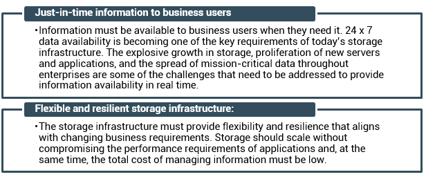
Organizations are experiencing an explosive growth in information. This information needs to be stored, protected, optimized, and managed efficiently. Data center managers are burdened with the challenging task of providing low-cost, high-performance information management solutions. An effective information management solution must provide the following:

Direct-attached storage (DAS) is often referred to as a stovepiped storage environment. Hosts “own” the storage, and it is difficult to manage and share resources on these isolated storage devices. Efforts to organize this dispersed data led to the emergence of the storage area network (SAN).

What is a SAN?
RAID

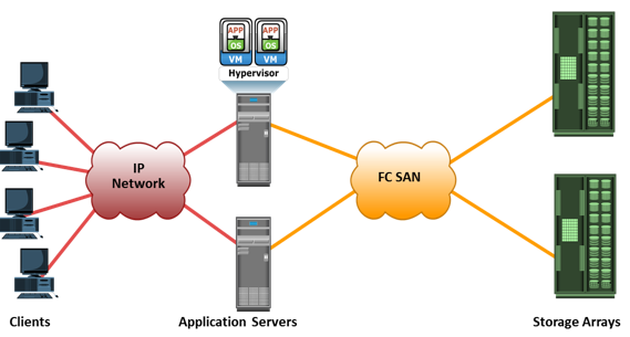
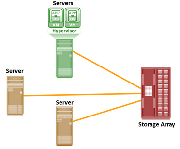
It is a high-speed, dedicated networ of severs and shared storage devices.

It enables storage consolidation and enables storage to be shared across multiple servers. This improves the utilization of storage resources compared to direct-attached storage architecture and reduces the total amount of storage an organization needs to purchase and manage. With consolidation, storage management becomes centralized and less complex, which further reduces the cost of managing information. SAN also enables organizations to connect geographically dispersed servers and storage. Further, it meets the storage demands efficiently with better economies of scale and also provides effective maintenance and protection of data.

Common SAN deployments are Fibre Channel (FC) SAN and IP SAN. Fibre Channel SAN uses Fibre Channel protocol for the transport of data, commands, and status information between servers (or hosts) and storage devices. IP SAN uses IP-based protocols for communication.

Understanding Fibre Channel

The FC architecture forms the fundamental construct of the FC SAN infrastructure. Fibre Channel is a high-speed network technology that runs on high-speed optical fiber cables and serial copper cables. The FC technology was developed to meet the demand for increased speeds of data transfer between servers and mass storage systems. Technical Committee T11, which is the committee within International Committee for Information Technology Standards (INCITS), is responsible for Fibre Channel interface standards.

High data transmission speed is an important feature of the FC networking technology. In comparison with Ultra-SCSI that is commonly used in DAS environments, FC is a significant leap in storage networking technology. The latest FC implementations of 16 GFC (Fibre Channel) offers a throughput of 3200 MB/s (raw bit rates of 16 Gb/s), whereas Ultra640 SCSI is available with a throughput of 640 MB/s. Credit-based flow control mechanism in FC delivers data as fast as the destination buffer is able to receive it, without dropping frames. Also FC has very little transmission overhead. The FC architecture is highly scalable, and theoretically, a single FC network can accommodate approximately 15 million devices.

Note: FibRE refers to the protocol, whereas fibER refers to a media.

Components of FC SAN

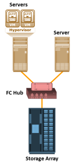
FC SAN is a network of servers and shared storage devices. Servers and storage are the end points or devices in the SAN (called ‘nodes’).  FC SAN infrastructure consists of node ports, cables, connectors, interconnecting devices (such as FC switches or hubs), along with SAN management software.

Node Ports

In a Fibre Channel network, the end devices, such as hosts, storage arrays, and tape libraries, are all referred to as nodes. Each node is a source or destination of information. Each node requires one or more ports to provide a physical interface for communicating with other nodes. These ports are integral components of host adapters, such as HBA, and storage front-end controllers or adapters. In an FC environment a port operates in full-duplex data transmission mode with a transmit (Tx) link and a receive (Rx) link.

Cables

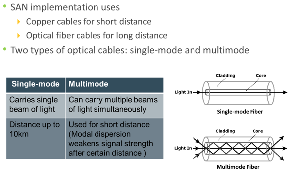
SAN implementations use optical fiber cabling. Copper can be used for shorter distances for back-end connectivity because it provides acceptable signal-to-noise ratio for distances up to 30 meters. Optical fiber cables carry data in the form of light. There are two types of optical cables: multimode and single-mode. Multimode fiber (MMF) cable carries multiple beams of light projected at different angles simultaneously onto the core of the cable. Based on the bandwidth, multimode fibers are classified as OM1 (62.5µm core), OM2 (50µm core), and laser-optimized OM3 (50µm core). In an MMF transmission, multiple light beams traveling inside the cable tend to disperse and collide. This collision weakens the signal strength after it travels a certain distance—a process known as modal dispersion. An MMF cable is typically used for short distances because of signal degradation (attenuation) due to modal dispersion.

Single-mode fiber (SMF) carries a single ray of light projected at the center of the core. These cables are available in core diameters of 7 to 11 microns; the most common size is 9 microns. In an SMF transmission, a single light beam travels in a straight line through the core of the fiber. The small core and the single light wave help to limit modal dispersion. Among all types of fiber cables, single-mode provides minimum signal attenuation over maximum distance (up to 10 km). A single-mode cable is used for long-distance cable runs, and distance usually depends on the power of the laser at the transmitter and sensitivity of the receiver.

MMFs are generally used within data centers for shorter distance runs, whereas SMFs are used for longer distances.
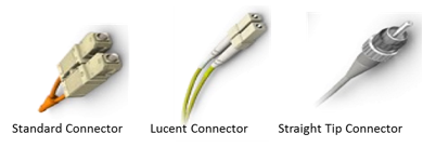
Connectors

A connector is attached at the end of a cable to enable swift connection and disconnection of the cable to and from a port. A Standard connector (SC) and a Lucent connector (LC) are two commonly used connectors for fiber optic cables. Straight Tip (ST) is another fiber-optic connector, which is often used with fiber patch panels.

Interconnecting Devices

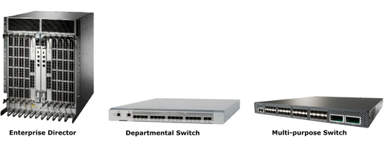
FC hubs, switches, and directors are the interconnect devices commonly used in FC SAN.

Hubs are used as communication devices in FC-AL implementations. Hubs physically connect nodes in a logical loop or a physical star topology. All the nodes must share the loop because data travels through all the connection points. Because of the availability of low-cost and high-performance switches, hubs are no longer used in FC SANs.

Switches are more intelligent than hubs and directly route data from one physical port to another. Therefore, nodes do not share the data path. Instead, each node has a dedicated communication path.

Directors are high-end switches with a higher port count and better fault-tolerance capabilities.

Switches are available with a fixed port count or with modular design. In a modular switch, the port count is increased by installing additional port cards to open slots. The architecture of a director is always modular, and its port count is increased by inserting additional line cards or blades to the director’s chassis. High-end switches and directors contain redundant components to provide high availability. Both switches and directors have management ports (Ethernet or serial) for connectivity to SAN management servers.

SAN Management Software

SAN management software manages the interfaces between hosts, interconnect devices, and storage arrays. The software provides a view of the SAN environment and enables management of various resources from one central console.
It provides key management functions, including mapping of storage devices, monitoring and generating alerts for discovered devices, and zoning (discussed later in the module).

FC Interconnectivity Options

The FC architecture supports three basic interconnectivity options: point-to-point, fibre channel arbitrated loop (FC-AL), and fibre channel switched fabric (FC-SW).

Connectors

Point-to-point is the simplest FC configuration—two devices are connected directly to each other, as shown in the slide. This configuration provides a dedicated connection for data transmission between nodes. However, the point-to-point configuration offers limited connectivity, because only two devices can communicate with each other at a given time. Moreover, it cannot be scaled to accommodate a large number of nodes. Standard DAS uses point-to-point connectivity.

FC-AL Connectivity

In the FC-AL configuration, devices are attached to a shared loop. FC-AL has the characteristics of a token ring topology and a physical star topology. In FC-AL, each device contends with other devices to perform I/O operations. Devices on the loop must “arbitrate” to gain control of the loop. At any given time, only one device can perform I/O operations on the loop

As a loop configuration, FC-AL can be implemented without any interconnecting devices by directly connecting one device to another two devices in a ring through cables.
However, FC-AL implementations may also use hubs whereby the arbitrated loop is physically connected in a star topology.

The FC-AL configuration has the following limitations in terms of scalability:

  • FC-AL shares the loop and only one device can perform I/O operations at a time. Because each device in a loop must wait for its turn to process an I/O request, overall performance in FC-AL environment is low.
  • FC-AL uses only 8-bits of 24-bit Fibre Channel addressing (the remaining 16-bits are masked) and enables the assignment of 127 valid addresses to the ports. Hence, it can support up to 127 devices on a loop. One address is reserved for optionally connecting the loop to an FC switch port. Therefore, up to 126 nodes can be connected to the loop.
  • Adding or removing a device results in loop re-initialization, which can cause a momentary pause in loop traffic.
FC-SW Connectivity

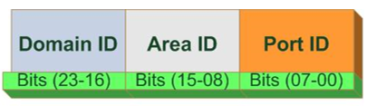
FC-SW is also referred to as fabric connect. A fabric is a logical space in which all nodes communicate with one another in a network. This virtual space can be created with a switch or a network of switches. Each switch in a fabric contains a unique domain identifier, which is part of the fabric’s addressing scheme. In FC-SW, nodes do not share a loop; instead, data is transferred through a dedicated path between the nodes. Each port in a fabric has a unique 24-bit Fibre Channel address for communication.

In a switched fabric, the link between any two switches is called an interswitch link (ISL). ISLs enable switches to be connected together to form a single, larger fabric. ISLs are used to transfer host-to-storage data and fabric management traffic from one switch to another. By using ISLs, a switched fabric can be expanded to connect a large number of nodes.
FC-SW uses switches that are intelligent devices. They can switch data traffic between nodes directly through switch ports. Frames are routed between source and destination by the fabric.

Unlike a loop configuration, a FC-SW network provides dedicated path and scalability. The addition or removal of a device in a switched fabric is minimally disruptive; it does not affect the ongoing traffic between other devices.

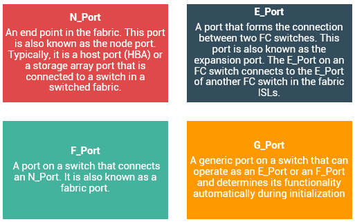
Port Types in Switched Fabric

Ports in a switched fabric can be one of the following types:

Lesson 2- Fibre Channel (FC) Architecture

Introduction


This lesson covers FC protocol stack, FC and WWN addressing, and structure and organization
of FC data. This lesson also covers fabric services and login types.

During this lesson the following topics are covered:

    • FC protocol stack
    • FC addressing
    • WWN addressing
    • Structure and organization of FC data
    • Fabric services
    • Fabric login types


Explanation


FC Architecture Overview

Traditionally, host computer operating systems have communicated with peripheral devices over channel connections, such as ESCON and SCSI. Channel technologies provide high levels of performance with low protocol overheads. Such performance is achievable due to the static nature of channels and the high level of hardware and software integration provided by the channel technologies. However, these technologies suffer from inherent limitations in terms of the number of devices that can be connected and the distance between these devices.
In contrast to channel technology, network technologies are more flexible and provide greater distance capabilities. Network connectivity provides greater scalability and uses shared bandwidth for communication. This flexibility results in greater protocol overhead and reduced performance.
The FC architecture represents true channel/network integration and captures some of the benefits of both channel and network technology. FC SAN uses the Fibre Channel Protocol (FCP) that provides both channel speed for data transfer with low protocol overhead and scalability of network technology.
FCP forms the fundamental construct of the FC SAN infrastructure. Fibre Channel provides a serial data transfer interface that operates over copper wire and optical fiber. FCP is the implementation of SCSI over an FC network. In FCP architecture, all external and remote storage devices attached to the SAN appear as local devices to the host operating system. The key advantages of FCP are as follows:

  • Sustained transmission bandwidth over long distances.
  • Support for a larger number of addressable devices over a network. Theoretically, FC can support more than 15 million device addresses on a network.
  • Support speeds up to 16 Gbps (16 GFC).
Fibre Channel Protocol Stack

It is easier to understand a communication protocol by viewing it as a structure of independent layers. FCP defines the communication protocol in five layers: FC-0 through FC-4 (except FC-3 layer, which is not implemented).

FC Addressing in Switched Fabric

An FC address is dynamically assigned when a node port logs on to the fabric. The FC address has a distinct format, as shown in the slide. The first field of the FC address contains the domain ID of the switch. A Domain ID is a unique number provided to each switch in the fabric. Although this is an 8-bit field, there are only 239 available addresses for domain ID because some addresses are deemed special and reserved for fabric management services. For example, FFFFFC is reserved for the name server, and FFFFFE is reserved for the fabric login service. The area ID is used to identify a group of switch ports used for connecting nodes. An example of a group of ports with common area ID is a port card on the switch. The last field, the port ID, identifies the port within the group.
Therefore, the maximum possible number of node ports in a switched fabric is calculated as: 239 domains X 256 areas X 256 ports = 15,663,104

World Wide Name (WWN)

Each device in the FC environment is assigned a 64-bit unique identifier called the World Wide Name (WWN). The Fibre Channel environment uses two types of WWNs: World Wide Node Name (WWNN) and World Wide Port Name (WWPN). Unlike an FC address, which is assigned dynamically, a WWN is a static name for each node on an FC network. WWNs are similar to the Media Access Control (MAC) addresses used in IP networking. WWNs are burned into the hardware or assigned through software. Several configuration definitions in a SAN use WWN for identifying storage devices and HBAs. The name server in an FC environment keeps the association of WWNs to the dynamically created FC addresses for nodes. Figure in the slide illustrates the WWN structure examples for an array and an HBA.

Structure and Organization of FC Data

In an FC network, data transport is analogous to a conversation between two people, whereby a frame represents a word, a sequence represents a sentence, and an exchange represents a conversation.

  • Exchange: An exchange operation enables two node ports to identify and manage a set of information units. Each upper layer protocol has its protocol-specific information that must be sent to another port to perform certain operations. This protocol-specific information is called an information unit. The structure of these information units is defined in the FC-4 layer. This unit maps to a sequence. An exchange is composed of one or more sequences.
  • Sequence: A sequence refers to a contiguous set of frames that are sent from one port to another. A sequence corresponds to an information unit, as defined by the ULP.
  • Frame: A frame is the fundamental unit of data transfer at Layer 2. An FC frame consists of five parts: start of frame (SOF), frame header, data field, cyclic redundancy check (CRC), and end of frame (EOF). The SOF and EOF act as delimiters. The frame header is 24 bytes long and contains addressing information for the frame. The data field in an FC frame contains the data payload, up to 2,112 bytes of actual data—in most cases, the SCSI data. The CRC checksum facilitates error detection for the content of the frame. This checksum verifies data integrity by checking whether the content of the frames was received correctly. The CRC checksum is calculated by the sender before encoding at the FC-1 layer. Similarly, it is calculated by the receiver after decoding at the FC-1 layer.

Fabric Services

All FC switches, regardless of the manufacturer, provide a common set of services as defined in the Fibre Channel standards. These services are available at certain predefined addresses. Some of these services are Fabric Login Server, Fabric Controller, Name Server, and Management Server.
The Fabric Login Server is located at the predefined address of FFFFFE and is used during the initial part of the node’s fabric login process.
The Name Server (formally known as Distributed Name Server) is located at the predefined address FFFFFC and is responsible for name registration and management of node ports.

Each switch exchanges its Name Server information with other switches in the fabric to maintain a synchronized, distributed name service.
Each switch has a Fabric Controller located at the predefined address FFFFFD.
The Fabric Controller provides services to both node ports and other switches. The Fabric Controller is responsible for managing and distributing Registered State Change Notifications (RSCNs) to the node ports registered with the Fabric Controller. If there is a change in the fabric, RSCNs are sent out by a switch to the attached node ports. The Fabric Controller also generates Switch Registered State Change Notifications (SW-RSCNs) to every other domain (switch) in the fabric. These RSCNs keep the name server up-to-date on all switches in the fabric.
FFFFFA is the Fibre Channel address for the Management Server. The Management Server is distributed to every switch within the fabric. The Management Server enables the FC SAN management software to retrieve information and administer the fabric.

Login Types in Switched Fabric

Lesson 3- FC SAN Topologies and Zoning

Introduction


This lesson covers FC SAN topologies such as mesh and core-edge. This lesson also covers zoning and its benefits, components, and types.

During this lesson the following topics are covered:

    • Mesh and core-edge topologies
    • Benefits of zoning
    • Types of zoning

Explanation


FC Architecture Overview

Traditionally, host computer operating systems have communicated with peripheral devices over channel connections, such as ESCON and SCSI. Channel technologies provide high levels of performance with low protocol overheads. Such performance is achievable due to the static nature of channels and the high level of hardware and software integration provided by the channel technologies. However, these technologies suffer from inherent limitations in terms of the number of devices that can be connected and the distance between these devices.
In contrast to channel technology, network technologies are more flexible and provide greater distance capabilities. Network connectivity provides greater scalability and uses shared bandwidth for communication. This flexibility results in greater protocol overhead and reduced performance.
The FC architecture represents true channel/network integration and captures some of the benefits of both channel and network technology. FC SAN uses the Fibre Channel Protocol (FCP) that provides both channel speed for data transfer with low protocol overhead and scalability of network technology.
FCP forms the fundamental construct of the FC SAN infrastructure. Fibre Channel provides a serial data transfer interface that operates over copper wire and optical fiber. FCP is the implementation of SCSI over an FC network. In FCP architecture, all external and remote storage devices attached to the SAN appear as local devices to the host operating system. The key advantages of FCP are as follows:

  • Sustained transmission bandwidth over long distances.
  • Support for a larger number of addressable devices over a network. Theoretically, FC can support more than 15 million device addresses on a network.
  • Support speeds up to 16 Gbps (16 GFC).
Mesh Topology

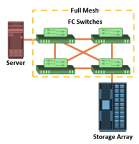
A mesh topology may be one of the two types: full mesh or partial mesh. In a full mesh, every switch is connected to every other switch in the topology.

A full mesh topology may be appropriate when the number of switches involved is small. A typical deployment would involve up to four switches or directors, with each of them servicing highly localized host-to- storage traffic. In a full mesh topology, a maximum of one ISL or hop is required for host-to- storage traffic. However, with the increase in the number of switches, the number of switch ports used for ISL also increases. This reduces the available switch ports for node connectivity.

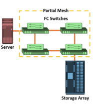
In a partial mesh topology, several hops or ISLs may be required for the traffic to reach its destination. Partial mesh offers more scalability than full mesh topology. However, without proper placement of host and storage devices, traffic management in a partial mesh fabric might be complicated and ISLs could become overloaded due to excessive traffic aggregation.

Core-edge Topology

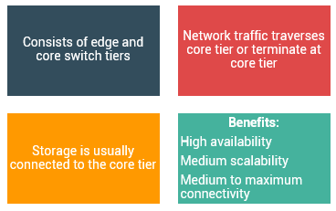
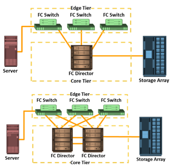
The core-edge fabric topology has two types of switch tiers. The edge tier is usually composed of switches and offers an inexpensive approach to adding more hosts in a fabric. Each switch at the edge tier is attached to a switch at the core tier through ISLs.

The core tier is usually composed of directors that ensure high fabric availability. In addition, typically all traffic must either traverse this tier or terminate at this tier. In this configuration, all storage devices are connected to the core tier, enabling host-to-storage traffic to traverse only one ISL. Hosts that require high performance may be connected directly to the core tier and consequently avoid ISL delays.

In core-edge topology, the edge-tier switches are not connected to each other. The core- edge fabric topology increases connectivity within the SAN while conserving the overall port utilization. If fabric expansion is required, additional edge switches are connected to the core. The core of the fabric is also extended by adding more switches or directors at the core tier. Based on the number of core-tier switches, this topology has different variations, such as, single-core topology and dual-core topology. To transform a single-core topology to dual- core, new ISLs are created to connect each edge switch to the new core switch in the fabric.

Zoning
Zoning

It is an FC switch function that enables node ports within the fabric to be logically segmented into groups, and communicate with each other within the group.

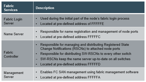
Whenever a change takes place in the name server database, the fabric controller sends a Registered State Change Notification (RSCN) to all the nodes impacted by the change. If zoning is not configured, the fabric controller sends an RSCN to all the nodes in the fabric. Involving the nodes that are not impacted by the change results in increased fabric- management traffic. For a large fabric, the amount of FC traffic generated due to this process can be significant and might impact the host-to-storage data traffic. Zoning helps to limit the number of RSCNs in a fabric. In the presence of zoning, a fabric sends the RSCN to only those nodes in a zone where the change has occurred.

Zoning also provides access control, along with other access control mechanisms, such as LUN masking. Zoning provides control by allowing only the members in the same zone to establish communication with each other.

Zone members, zones, and zone sets form the hierarchy defined in the zoning process. A zone set is composed of a group of zones that can be activated or deactivated as a single entity in a fabric. Multiple zone sets may be defined in a fabric, but only one zone set can be active at a time. Members are nodes within the SAN that can be included in a zone. Switch ports, HBA ports, and storage device ports can be members of a zone. A port or node can be a member of multiple zones. Nodes distributed across multiple switches in a switched fabric may also be grouped into the same zone. Zone sets are also referred to as zone configurations.

Types of Zoning

Zoning can be categorized into three types:

Figure in the slide shows the three types of zoning on an FC network.

Lesson 4- Virtualization in SAN

Introduction


This lesson covers block-level storage virtualization and virtual SAN.

During this lesson the following topics are covered:

    • Block-level storage virtualization
    • Virtual SAN

Explanation


Block-level Storage Virtualization

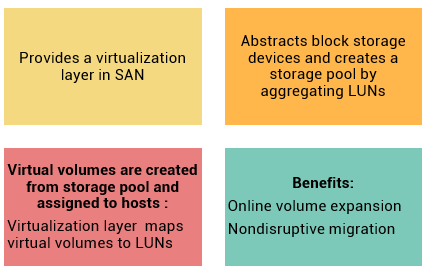
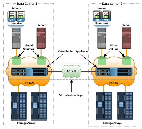
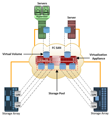
Block-level storage virtualization aggregates block storage devices (LUNs) and enables provisioning of virtual storage volumes, independent of the underlying physical storage. A virtualization layer, which exists at the SAN, abstracts the identity of physical storage devices and creates a storage pool from heterogeneous storage devices. Virtual volumes are created from the storage pool and assigned to the hosts. Instead of being directed to the LUNs on the individual storage arrays, the hosts are directed to the virtual volumes provided by the virtualization layer. For hosts and storage arrays, the virtualization layer appears as the target and initiator devices, respectively. The virtualization layer maps the virtual volumes to the LUNs on the individual arrays. The hosts remain unaware of the mapping operation and access the virtual volumes as if they were accessing the physical storage attached to them. Typically, the virtualization layer is managed via a dedicated virtualization appliance to which the hosts and the storage arrays are connected.

Figure in the slide illustrates a virtualized environment. It shows two physical servers, each of which has one virtual volume assigned. These virtual volumes are used by the servers. These virtual volumes are mapped to the LUNs in the storage arrays. When an I/O is sent to a virtual volume, it is redirected through the virtualization layer at the storage network to the mapped LUNs. Depending on the capabilities of the virtualization appliance, the architecture may allow for more complex mapping between array LUNs and virtual volumes.

Block-level storage virtualization enables extending the storage volumes online to meet application growth requirements. It consolidates heterogeneous storage arrays and enables transparent volume access.

Block-level storage virtualization also provides the advantage of nondisruptive data migration. In a traditional SAN environment, LUN migration from one array to another is an offline event because the hosts needed to be updated to reflect the new array configuration. In other instances, host CPU cycles were required to migrate data from one array to the other, especially in a multivendor environment. With a block-level virtualization solution in place, the virtualization layer handles the back-end migration of data, which enables LUNs to remain online and accessible while data is migrating. No physical changes are required because the host still points to the same virtual targets on the virtualization layer. However, the mappings information on the virtualization layer should be changed. These changes can be executed dynamically and are transparent to the end user.

Use Case: Block-level Storage Virtualization across Data Centers

Previously, block-level storage virtualization provided nondisruptive data migration only within a data center. The new generation of block-level storage virtualization enables nondisruptive data migration both within and between data centers. It provides the capability to connect the virtualization layers at multiple data centers. The connected virtualization layers are managed centrally and work as a single virtualization layer stretched across data centers. This enables the federation of block-storage resources both within and across data centers. The virtual volumes are created from the federated storage resources.

Virtual SAN (VSAN)/Virtual Fabric
VSAN

It is a logical fabric on an FC SAN, enabling communication among a group of nodes, regardless of their physical location in the fabric.

In a VSAN, a group of hosts or storage ports communicate with each other using a virtual topology defined on the physical SAN. Multiple VSANs may be created on a single physical SAN. Each VSAN acts as an independent fabric with its own set of fabric services, such as name server, and zoning. Fabric-related configurations in one VSAN do not affect the traffic in another.

VSANs improve SAN security, scalability, availability, and manageability. VSANs provide enhanced security by isolating the sensitive data in a VSAN and by restricting access to the resources located within that VSAN.

The same Fibre Channel address can be assigned to nodes in different VSANs, thus increasing the fabric scalability. Events causing traffic disruptions in one VSAN are contained within that VSAN and are not propagated to other VSANs.

VSANs facilitate an easy, flexible, and less expensive way to manage networks.

Configuring VSANs is easier and quicker compared to building separate physical FC SANs for various node groups. To regroup nodes, an administrator simply changes the VSAN configurations without moving nodes and recabling.

EMC Connectrix

The Concept in Practice section covers EMC Connectrix and VPLEX.

The EMC Connectrix family represents the industry’s most extensive selection of networked storage connectivity products. Connectrix integrates high-speed FC connectivity, highly resilient switching technology, options for intelligent IP storage networking, and I/O consolidation with products that support Fibre Channel over Ethernet (FCoE). The connectivity products offered under the Connectrix brand are: Enterprise directors, departmental switches, and multi-purpose switches .
Enterprise directors offer high port density and high component redundancy. They are deployed in high-availability or large-scale environments. Connectrix directors offer several hundred ports per domain. Departmental switches are best suited for workgroup, mid-tier environments. Multi-purpose switches support various protocols such as iSCSI, FCIP, FCoE, FICON, in addition to FC protocol. In addition to FC ports, Connectrix switches and directors have Ethernet ports and serial ports for communication and switch management functions..

EMC ControlCenter SAN Manager provides a single interface for managing a SAN. With SAN Manager, an administrator can discover, monitor, manage, and configure complex heterogeneous SAN environments. It streamlines and centralizes SAN management operations across multivendor storage networks and storage devices. It enables storage administrators to manage SAN zones and LUN masking consistently across multivendor SAN arrays and switches. EMC ControlCenter SAN Manager also supports virtual environments, including VMware, and virtual SANs.
EMC ProSphere is a newly launched tool with additional features specifically for the cloud computing environment. A future release of EMC ProSphere will include all the functionalities of EMC ControlCenter.

EMC Connectrix
  • Connectrix family includes networked storage connectivity products
    • Offers high-speed FC connectivity, highly resilient switching technology, intelligent IP storage networking, and I/O consolidation with Fibre Channel over Ethernet
  • Connectrix family consist of enterprise directors, departmental switches, and multi-purpose switches

EMC VPLEX is the next-generation solution for block-level virtualization and data mobility both within and across datacenters. The VPLEX appliance resides between the servers and heterogeneous storage devices. It forms a pool of distributed block storage resources and enables creating virtual storage volumes from the pool. These virtual volumes are then allocated to the servers. The virtual-to-physical-storage mapping remains hidden to the servers.

VPLEX provides nondisruptive data mobility among physical storage devices to balance the application workload and to enable both local and remote data access. The mapping of virtual volumes to physical volumes can be changed dynamically by the administrator.

VPLEX uses a unique clustering architecture and distributed cache coherency that enable multiple hosts located across two locations to access a single copy of data. VPLEX also provides the capability to mirror data of a virtual volume both within and across locations. This enables hosts at different data centers to access cache-coherent copies of the same virtual volume. To avoid application downtime due to outage at a data center, the workload can be moved quickly to another data center. Applications continue accessing the same virtual volume and remain uninterrupted by the data mobility.

The VPLEX family consists of three products: VPLEX Local, VPLEX Metro, and VPLEX Geo.

EMC VPLEX Local delivers local federation, which provides simplified management and nondisruptive data mobility across heterogeneous arrays within a data center. EMC VPLEX Metro delivers distributed federation, which provides data access and mobility between two VPEX clusters within synchronous distances that support round-trip latency up to 5 ms. EMC VPLEX Geo delivers data access and mobility between two VPLEX clusters within asynchronous distances (that support round-trip latency up to 50 ms).

Summary


This module covered FC SAN components – node port, cable, connector, interconnecting devices, and SAN management software; FC connectivity options – point-to-point, FC-AL, FC- SW; and fabric port types such as N_Port, E_Port, F_Port, and G_Port. It includes FC protocol stack and addressing, structure and organization of FC data, and fabric services and login types. This module also covered fabric topologies – core-edge and mesh; types of zoning – port, WWN, and mixed; block-level storage virtualization; and virtual SAN.

Checkpoint


  • FC SAN components and connectivity options
  • FC protocol stack and addressing
  • Structure and organization of FC data
  • Fabric services
  • Fabric topologies
  • Types of zoning
  • Block-level storage virtualization and virtual SAN

Bibliographic references


EMC Proven Professional. Copyright © 2012 EMC Corporation. All rights reserved