Two primary protocols that leverage IP as the transport mechanism are Internet SCSI (iSCSI) and Fibre Channel over IP (FCIP). This lesson covers the drivers for IP SAN and iSCSI components, topologies, protocol stack, and discovery methods. It also covers FCIP protocol stack and topology.
Drivers for IP SAN
Traditional SAN enables the transfer of block I/O over Fibre Channel and provides high performance and scalability. These advantages of FC SAN come with the additional cost of buying FC components, such as FC HBA and switches. Organizations typically have an existing Internet Protocol (IP)-based infrastructure, which could be leveraged for storage networking. Advancements in technology have enabled IP to be used for transporting block I/O over the IP network. This technology of transporting block I/Os over an IP is referred to as IP SAN. IP is a mature technology, and using IP as a storage networking option provides several advantages. When block I/O is run over IP, the existing network infrastructure can be leveraged, which is more economical than investing in a new SAN infrastructure. In addition, many robust and mature security options are now available for IP networks. Many long- distance, disaster recovery (DR) solutions are already leveraging IP-based networks. With IP SAN, organizations can extend the geographical reach of their storage infrastructure.
IP SAN Protocol: iSCSI
iSCSI is encapsulation of SCSI I/O over IP. iSCSI is an IP based protocol that establishes and manages connections between host and storage over IP. iSCSI encapsulates SCSI commands and data into an IP packet and transports them using TCP/IP. iSCSI is widely adopted for connecting servers to storage because it is relatively inexpensive and easy to implement, especially environments in which an FC SAN does not exist
RAID
- IP based protocol that is used to connect host and storage
- Encapsulates SCSI commands and data into an IP packet and transports them using TCP/IP
IPComponents of iSCSI
An initiator (host), target (storage or iSCSI gateway), and an IP-based network are the key iSCSI components. If an iSCSI-capable storage array is deployed, then a host with the iSCSI initiator can directly communicate with the storage array over an IP network. However, in an implementation that uses an existing FC array for iSCSI communication, an iSCSI gateway is used. These devices perform the translation of IP packets to FC frames and vice versa, thereby bridging the connectivity between the IP and FC environments.
iSCSI initiator:
iSCSI target:
- Storage array with iSCSI port
- iSCSI gateway – enables communication with FC storage array
IP network
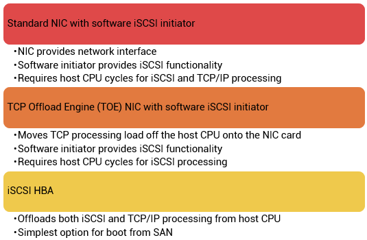
iSCSI Host Connectivity Options
A standard NIC with software iSCSI initiator, a TCP offload engine (TOE) NIC with software iSCSI initiator, and an iSCSI HBA are the three iSCSI host connectivity options. The function of the iSCSI initiator is to route the SCSI commands over an IP network.
A standard NIC with a software iSCSI initiator is the simplest and least expensive connectivity option. It is easy to implement because most servers come with at least one, and in many cases two, embedded NICs. It requires only a software initiator for iSCSI functionality.
Because NICs provide standard IP function, encapsulation of SCSI into IP packets and decapsulation are carried out by the host CPU. This places additional overhead on the host CPU. If a standard NIC is used in heavy I/O load situations, the host CPU might become a bottleneck. TOE NIC helps alleviate this burden. A TOE NIC offloads TCP management functions from the host and leaves only the iSCSI functionality to the host processor. The host passes the iSCSI information to the TOE card, and the TOE card sends the information to the destination using TCP/IP. Although this solution improves performance, the iSCSI functionality is still handled by a software initiator that requires host CPU cycles.
An iSCSI HBA is capable of providing performance benefits because it offloads the entire iSCSI and TCP/IP processing from the host processor. The use of an iSCSI HBA is also the simplest way to boot hosts from a SAN environment via iSCSI. If there is no iSCSI HBA, modifications must be made to the basic operating system to boot a host from the storage devices because the NIC needs to obtain an IP address before the operating system loads. The functionality of an iSCSI HBA is similar to the functionality of an FC HBA.
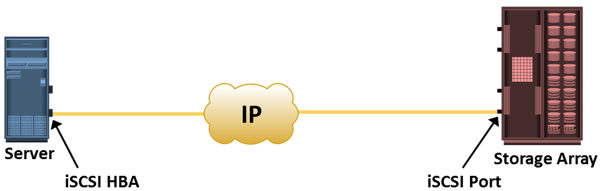
iSCSI Topologies: Native iSCSI
Two topologies of iSCSI implementations are native and bridged. Native topology does not have FC components. The initiators may be either directly attached to targets or connected through the IP network.
FC components are not required for iSCSI connectivity if an iSCSI-enabled array is deployed. In figure in the slide, the array has one or more iSCSI ports configured with an IP address and connected to a standard Ethernet switch. After an initiator is logged on to the network, it can access the available LUNs on the storage array. A single array port can service multiple hosts or initiators as long as the array port can handle the amount of storage traffic that the hosts generate.
iSCSI Topologies: Bridged iSCSI
Bridged topology enables the coexistence of FC with IP by providing iSCSI-to-FC bridging functionality.
Figure illustrates an iSCSI host connectivity to an FC storage array. In this case, the array does not have any iSCSI ports. Therefore, an external device, called a gateway or a multiprotocol router, must be used to facilitate the communication between the iSCSI host and FC storage.
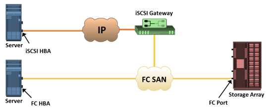
The gateway converts IP packets to FC frames and vice versa.
The bridge devices contain both FC and Ethernet ports to facilitate the communication between the FC and IP environments. In bridged iSCSI implementation, the iSCSI initiator is configured with the gateway’s IP address as its target destination. On the other side, the gateway is configured as an FC initiator to the storage array.
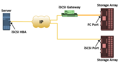
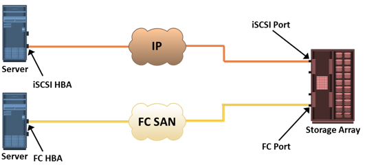
Combining FC and Native iSCSI Connectivity
The most common topology is a combination of FC and native iSCSI. Typically, a storage array comes with both FC and iSCSI ports that enable iSCSI and FC connectivity in the same environment, as shown in the figure.
iSCSI Protocol Stack
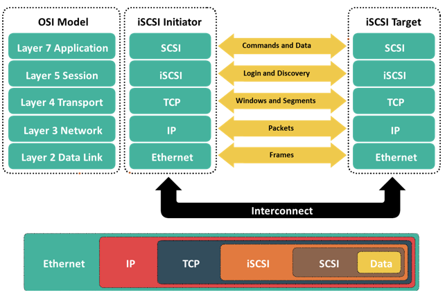
Figure displays a model of the iSCSI protocol layers and depicts the encapsulation order of the SCSI commands for their delivery through a physical carrier.
SCSI is the command protocol that works at the application layer of the Open System Interconnection (OSI) model. The initiators and targets use SCSI commands and responses to talk to each other. The SCSI command descriptor blocks, data, and status messages are encapsulated into TCP/IP and transmitted across the network between the initiators and targets.
iSCSI is the session-layer protocol that initiates a reliable session between devices that recognize SCSI commands and TCP/IP. The iSCSI session-layer interface is responsible for handling login, authentication, target discovery, and session management. TCP is used with iSCSI at the transport layer to provide reliable transmission.
TCP controls message flow, windowing, error recovery, and retransmission. It relies upon the network layer of the OSI model to provide global addressing and connectivity. The Layer 2 protocols at the data link layer of this model enable node-to-node communication through a physical network.
iSCSI Discovery
An initiator must discover the location of its targets on the network and the names of the targets available to it before it can establish a session. This discovery can take place in two ways: SendTargets discovery or internet Storage Name Service (iSNS).
In SendTargets discovery, the initiator is manually configured with the target’s network portal to establish a discovery session. The initiator issues the SendTargets command, and the target network portal responds with the required parameters of the targets available to the host.
iSNS enables automatic discovery of iSCSI devices on an IP network. The initiators and targets can be configured to automatically register themselves with the iSNS server. Whenever an initiator wants to know the targets that it can access, it can query the iSNS server for a list of available targets.
iSCSI Name
A unique worldwide iSCSI identifier, known as an iSCSI name, is used to identify the initiators and targets within an iSCSI network to facilitate communication. The unique identifier can be a combination of the names of the department, application, or manufacturer, serial number, asset number, or any tag that can be used to recognize and manage the devices. Following are two types of iSCSI names commonly used:
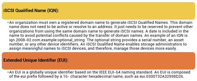
In either format, the allowed special characters are dots, dashes, and blank spaces.
IP SAN Protocol: FCIP
FC SAN provides a high-performance infrastructure for localized data movement. Organizations are now looking for ways to transport data over a long distance between their disparate SANs at multiple geographic locations. One of the best ways to achieve this goal is to interconnect geographically dispersed SANs through reliable, high-speed links. This approach involves transporting the FC block data over the IP infrastructure. FCIP is a tunneling protocol that enables distributed FC SAN islands to be interconnected over the existing IP-based networks.
FCIP is a protocol in which FCIP entity such as FCIP gateway is used to tunnel FC fabrics through an IP network. In FCIP FC frames are encapsulated onto the IP payload. An FCIP implementation is capable to merge interconnected fabrics into a single fabric. Frequently, only a small subset of nodes at either end requires connectivity across fabrics. Thus, the majority of FCIP implementations today use switch-specific features such as IVR (Inter-VSAN Routing) or FCRS (Fibre Channel Routing Services) to create a tunnel. In this manner, traffic may be routed between specific nodes without actually merging the fabrics.
The FCIP standard has rapidly gained acceptance as a manageable, cost-effective way to blend the best of the two worlds: FC SAN and the proven, widely deployed IP infrastructure. As a result, organizations now have a better way to store, protect, and move their data by leveraging investments in their existing IP infrastructure. FCIP is extensively used in disaster
recovery implementations in which data is duplicated to the storage located at a remote site.
FCIP Topology
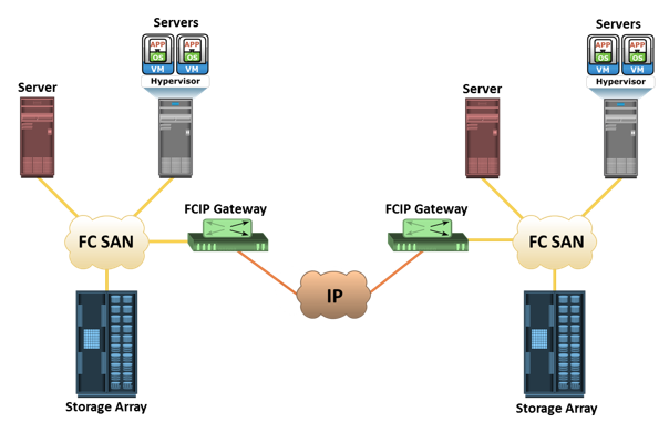
In an FCIP environment, an FCIP gateway is connected to each fabric via a standard FC connection. The FCIP gateway at one end of the IP network encapsulates the FC frames into IP packets. The gateway at the other end removes the IP wrapper and sends the FC data to the layer 2 fabric. The fabric treats these gateways as layer 2 fabric switches. An IP address is assigned to the port on the gateway, which is connected to an IP network. After the IP connectivity is established, the nodes in the two independent fabrics can communicate with other.
FCIP Protocol Stack
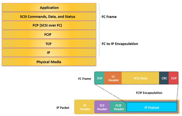
The FCIP protocol stack is shown in the slide. Applications generate SCSI commands and data, which are processed by various layers of the protocol stack. The upper layer protocol SCSI includes the SCSI driver program that executes the read-and-write commands. Below the SCSI layer is the Fibre Channel Protocol (FCP) layer, which is simply a fibre channel frame whose payload is SCSI. The FCP layer rides on top of the Fibre Channel transport layer. This enables the FC frames to run natively within a SAN fabric environment. In addition, the FC frames can be encapsulated into the IP packet and sent to a remote SAN over the IP. The FCIP layer encapsulates the Fibre Channel frames onto the IP payload and passes them to the TCP layer. TCP and IP are used for transporting the encapsulated information across Ethernet, wireless, or other media that support the TCP/IP traffic.
Encapsulation of FC frame on to IP packet could cause the IP packet to be fragmented when the data link cannot support the maximum transmission unit (MTU) size of an IP packet. When an IP packet is fragmented, the required parts of the header must be copied by all fragments. When a TCP packet is segmented, normal TCP operations are responsible for receiving and re-sequencing the data prior to passing it on to the FC processing portion of the device.


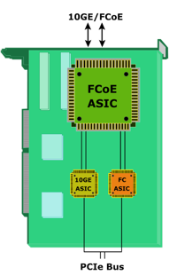 A CNA provides the functionality of both a standard NIC and an FC HBA in a single adapter and consolidates both types of traffic. CNA eliminates the need to deploy separate adapters and cables for FC and Ethernet communications, thereby reducing the required number of server slots and switch ports. CNA offloads the FCoE protocol processing task from the server, thereby freeing the server CPU resources for application processing. A CNA contains separate modules for 10 Gigabit Ethernet, Fibre Channel, and FCoE Application Specific Integrated Circuits (ASICs). The FCoE ASIC encapsulate FC frames into Ethernet frames. One end of this ASIC is connected to 10GbE and FC ASICs for server connectivity, while the other end provides a 10GbE interface to connect to an FCoE switch.
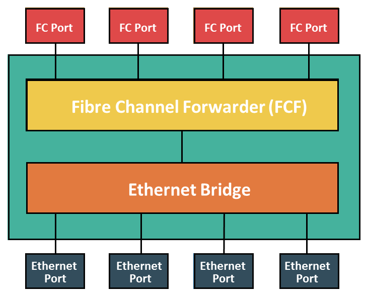 An FCoE switch has both Ethernet switch and Fibre Channel switch functionalities. The FCoE switch has a Fibre Channel Forwarder (FCF), Ethernet Bridge, and set of Ethernet ports and optional FC ports. The function of the FCF is to encapsulate the FC frames, received from the FC port, into the FCoE frames and also to de-encapsulate the FCoE frames, received from the Ethernet Bridge, to the FC frames.
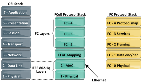
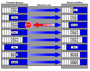 Traditional FC manages congestion through the use of a link-level, credit-based flow control that guarantees no loss of frames. Typical Ethernet, coupled with TCP/IP, uses a packet drop flow control mechanism. The packet drop flow control is not lossless. This challenge is eliminated by using an IEEE 802.3x Ethernet PAUSE control frame to create a lossless Ethernet. A receiver can send a PAUSE request to a sender when the receiver’s buffer is filling up. Upon receiving a PAUSE frame, the sender stops transmitting frames, which guarantees no loss of frames. The downside of using the Ethernet PAUSE frame is that it operates on the entire link, which might be carrying multiple traffic flows.


